IZSVES User Guide
Strobe Illuminator Series
Click to show the Table of Contents
- 1. Recommended Reading/Related Documents
- 2. Training and Support
- 3. Overview
- 4. Required Accessories (Not Included)
- 5. Planning Your Installation
- 6. Mounting and Aiming
- 7. Connecting the Illuminator to the Camera System
- 8. Configuration
- 9. Verifying Infrared-type Operation
- 10. Maintenance
- 11. Notices, Safety Precautions and Certifications
1. Recommended Reading/Related Documents
Click to show the Related Documents table
| Doc. No. | Title |
|---|---|
IZA800GVES Installation Guide |
|
Illuminator Cable for VES System Technical Data Sheet |
|
Product-to-Mount Mapping |
|
Illuminator Mounting - U.S.A. |
|
Illuminator Gantry Mounting - Using Packaged Hardware |
|
NDAA Section 889 Certification of Compliance |
2. Training and Support
2.1. Training
This document does not take the place of training by Inex Technologies' certified specialists. Contact Inex Technologies to schedule training.
2.2. Support
If you have any questions, please contact our support team via our Inex Technologies Website.
3. Overview
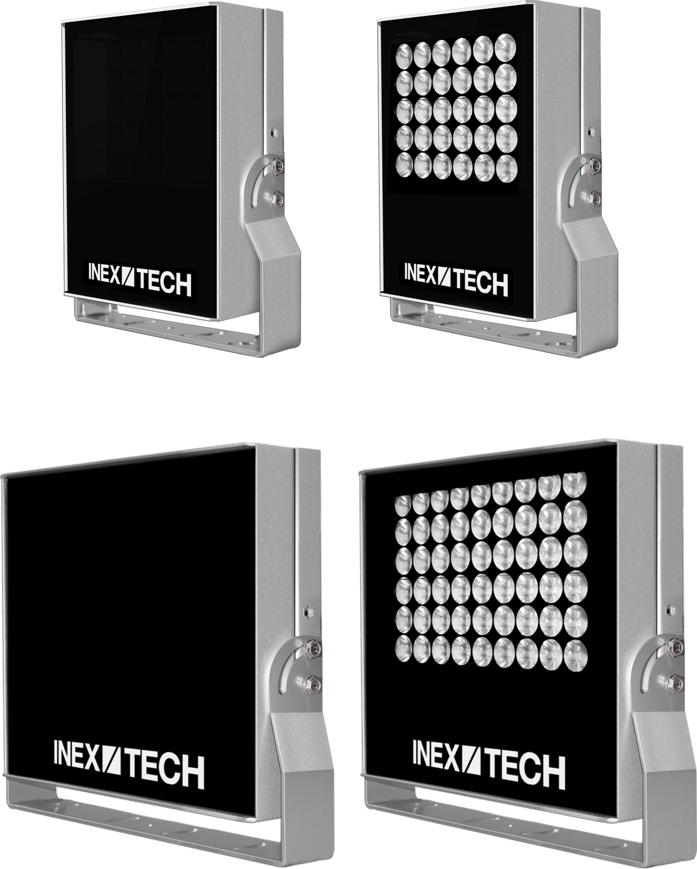
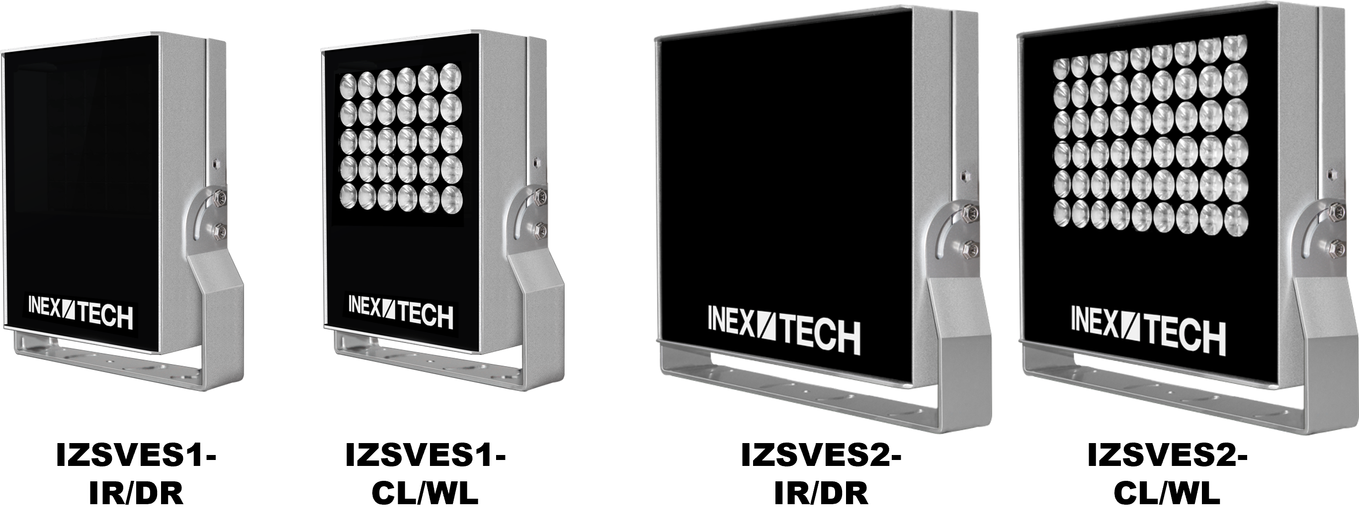
3.1. Illuminator Models
The illuminator model codes are IZSVES[1/2]-(IR/DR/CL/WL)-10/20/30/H40/60/H120, where:
-
After IZSVES:
-
1/2 - number of LEDs: 1=30, 2=60
-
WVLN = Wavelength/type of LEDs:
-
IR - Infrared
-
DR - Deep Red
-
CL - Cool White (4000K)
-
WL - Warm White (3000K)
-
-
10/20/30/H40/60/H120 - LED beam angle, in degrees (Notes: H40 = H40xV15; H120xV20-degree model available as IZSVES2-IR-H120)
3.2. Package Contents
Carefully unpack the contents of the package (your illuminator model may look different than the ones shown here).
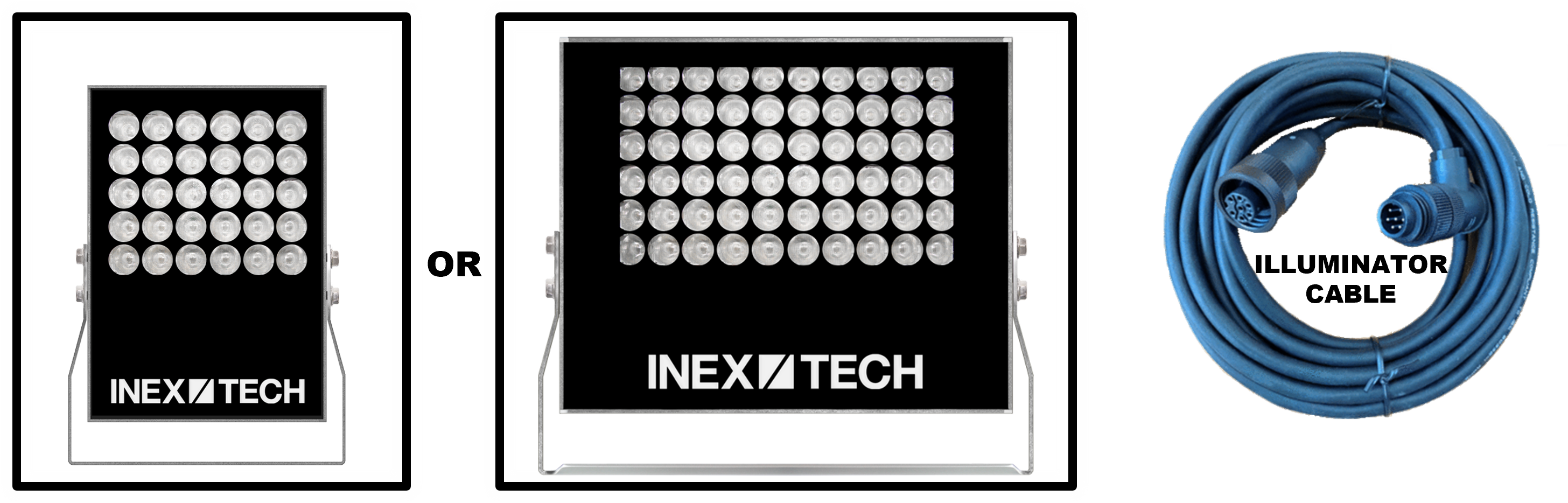
The package includes:
-
Illuminator with outer pan/tilt adjustment bracket
-
Illuminator cable, 15 ft (4.6 m); different IZCAB-SVES cable lengths can be ordered
-
QC sheet
|
Mounting hardware may be included in your package, or packed separately, depending on your site’s requirements. See the Mounting Hardware documentation (see Section 1). If any parts are missing or damaged, please contact Inex Technologies. |
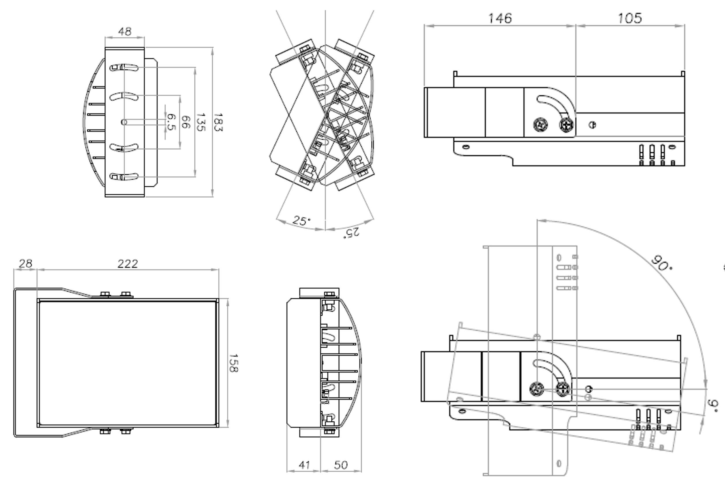
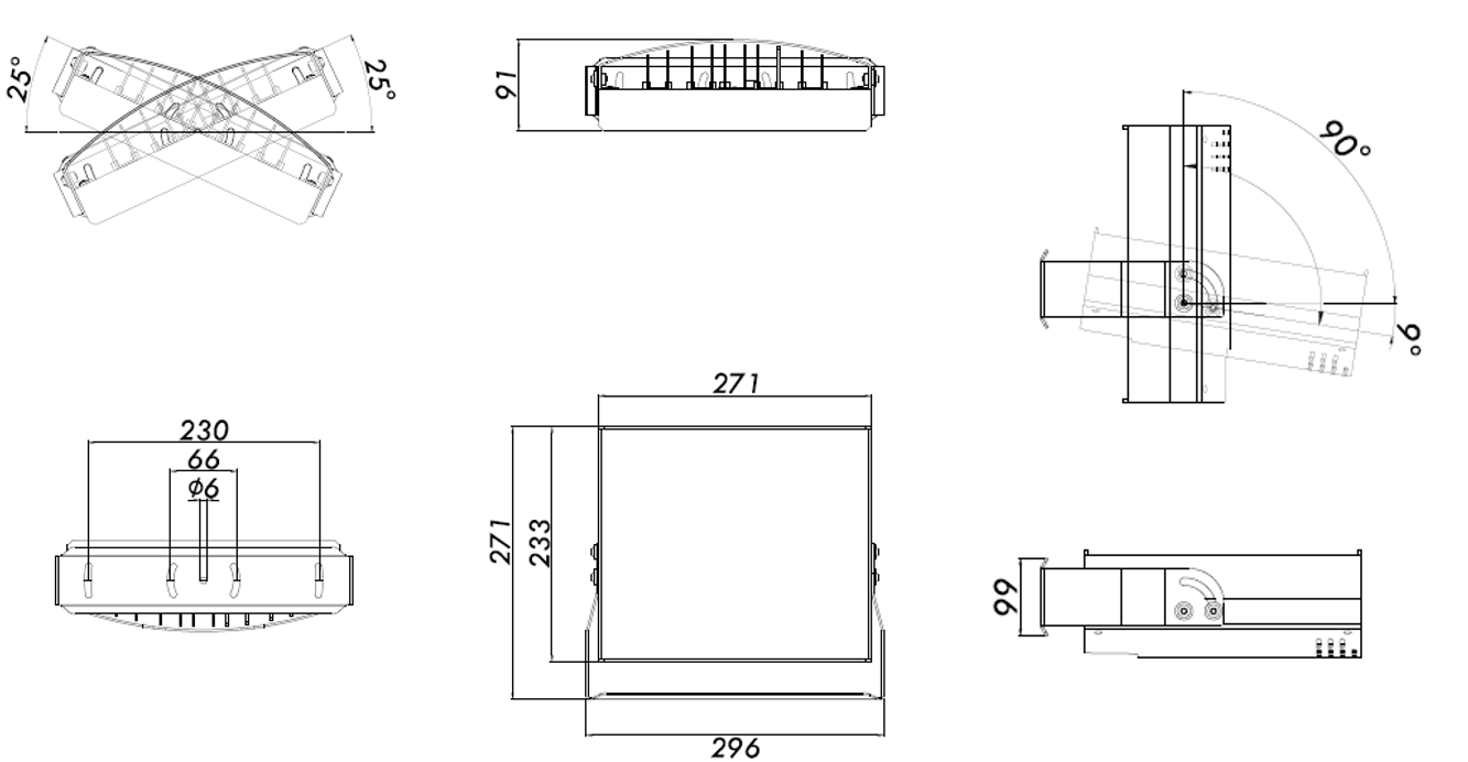
3.3. Dimensions and Specifications
| Item | Specification | |||||||||||||||
|---|---|---|---|---|---|---|---|---|---|---|---|---|---|---|---|---|
LED Illumination |
Type |
High power LEDs |
||||||||||||||
Flash Activation |
Activated by strobe input (3.3 - 24 VDC, opto-isolated) |
|||||||||||||||
Wavelength (WVLN) |
|
|||||||||||||||
Number of LEDs (N) |
|
|||||||||||||||
Beam Angle (HxV), |
|
|||||||||||||||
Environmental |
Ingress Protection |
IP66 |
||||||||||||||
Operating Temperature |
-13°F to 140°F (-25°C to 60°C) |
|||||||||||||||
Humidity |
0% to 90% RH |
|||||||||||||||
Certifications |
EMC |
FCC Class B/CE |
||||||||||||||
RoHS |
RoHS |
|||||||||||||||
Eye Safety |
IEC62471:
|
|||||||||||||||
NDAA |
NDAA Section 889 compliant |
|||||||||||||||
Physical |
Dimensions |
|
||||||||||||||
Unit Weight* |
|
|||||||||||||||
Material |
Anodized Aluminum |
|||||||||||||||
Color |
Silver |
|||||||||||||||
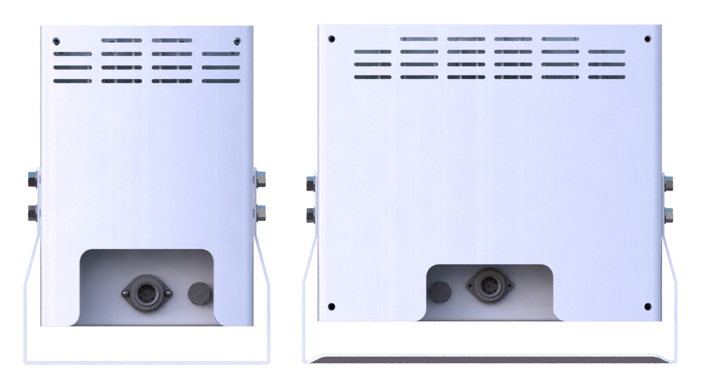
Interface |
Connector |
Power/Strobe/Configuration: |
||||||||||||||
Configuration Communication Protocol |
RS485 |
|||||||||||||||
Strobe Input |
3.3 - 24VDC, opto-isolated |
|||||||||||||||
Power |
Input Voltage |
24 VDC** |
||||||||||||||
Power Consumption (measured with 0.5 ms pulse width; 24 VDC input) |
|
|||||||||||||||
Accessories Included |
2-axis outer pan/tilt adjustment bracket |
|||||||||||||||
Illuminator cable, 15 ft (4.6 m) |
||||||||||||||||
Accessories Available (depending on site requirements) |
Illuminator Cable |
Illuminator Cable for IZSVES Illuminator (IZCAB-SVES) - different lengths |
||||||||||||||
Mounting hardware (in package) |
|
|||||||||||||||
Mounting hardware (packed separately) |
Wall/pole/gantry mounting options |
|||||||||||||||
Power Supply |
Power Supply 24 VDC** |
|||||||||||||||
* Including outer pan/tilt adjustment bracket
4. Required Accessories (Not Included)
-
See the Mounting Hardware documentation for a list of required tools (see Section 1).
5. Planning Your Installation
5.1. Matching an Illuminator to Your Camera System
-
The wavelength of an external illuminator must be compatible with the wavelength of the internal illuminators of the Inex Camera System.
-
The number of illuminator LEDs and beam angle must match the distance rating of the camera being used, as follows:
-
Fewer LEDs and wider beam angles are used for short distances
-
More LEDs and narrower beam angles are used for longer distances
-
See your Camera System’s Installation Guide for a table of Camera-to-Illuminator Recommended Setups.
5.2. Additional Installation Considerations
| Item | Considerations |
|---|---|
Surge Protection |
|
Cable Lengths IMPORTANT |
Illuminator Cable: Use a cable length long enough to:
|
Mounting |
|
-
Position the illuminator so you can aim it at the place where vehicles pass for recognition - while minimizing the glare into drivers' eyes. In most cases, however, white illuminators are mounted to be aimed at the rear of vehicles. Illuminator aiming is most effective at night.
6. Mounting and Aiming
6.1. Overall Mounting Considerations
-
Mounting hardware may be included in your package, or packed separately, depending on your site’s requirements. See the Mounting Hardware documentation (see Section 1).
-
Mount illuminators at an appropriate distance away from their associated camera(s), according to the objectives of your project. Contact Inex for guidance/training about this subject.
6.2. Aiming the Illuminator
See your Camera System’s User Guide for details on how to adjust the position of the camera to optimize license plate recognition. As part of this process, you may need to adjust the tilt and/or pan of the illuminator.
For instructions on how to adjust the pan and tilt, see the Mounting Hardware documentation (see Section 1).
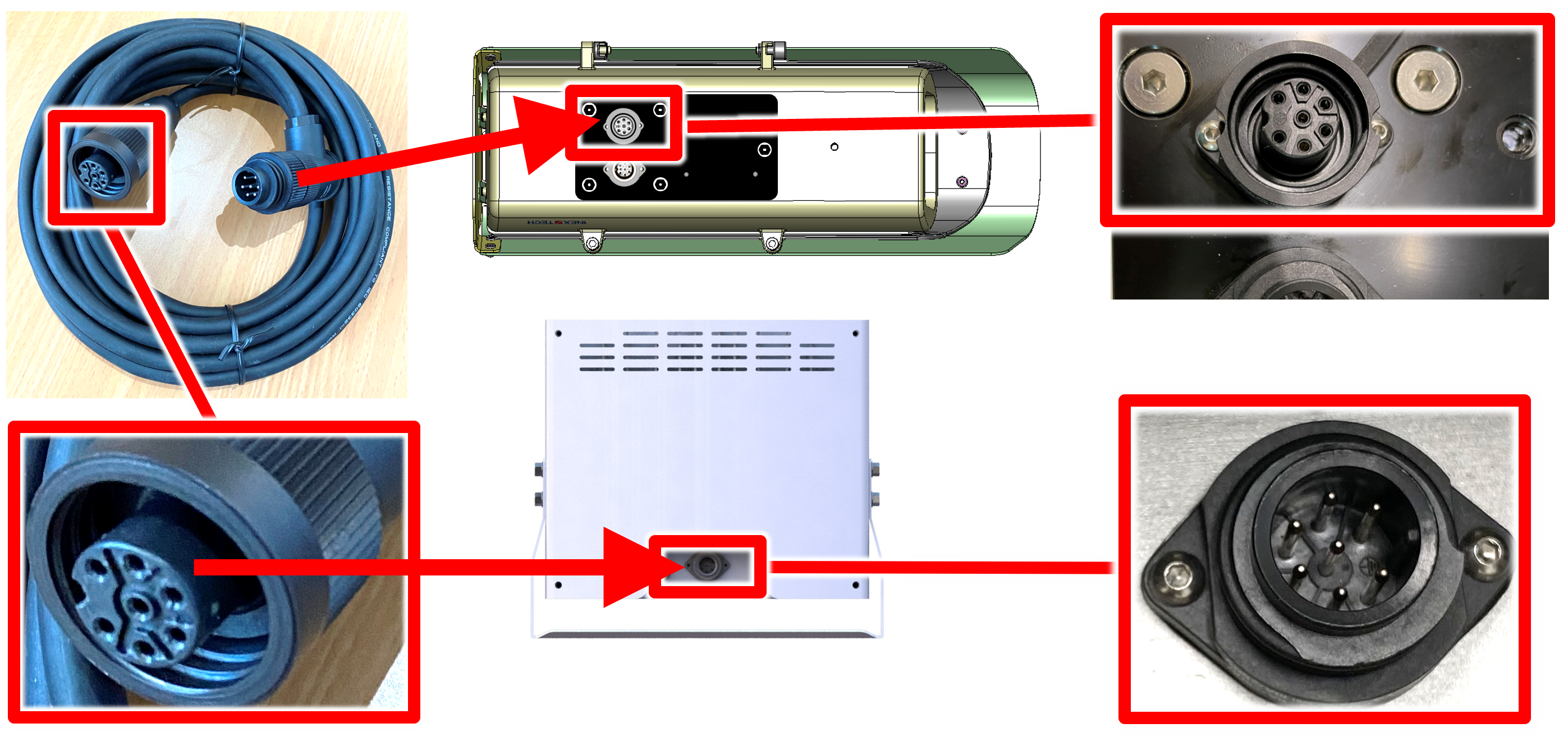
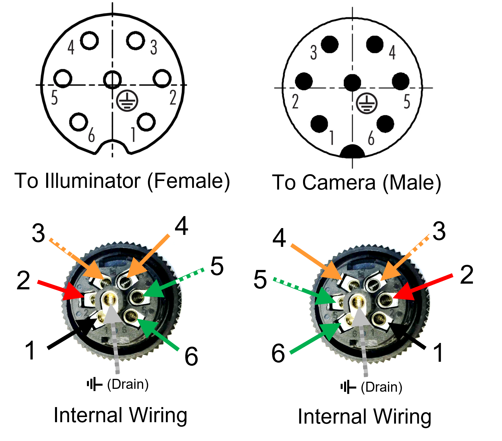
7. Connecting the Illuminator to the Camera System
|
Turn off/disconnect the external (AC) power supply before connecting cables. |
|
If you need to use a longer illuminator cable (see Section 5.2), be sure that: the supplied voltage (24 VDC) reaches the illuminator, the strobe signal levels you need reach the illuminator, and the RS485 signal levels reach the illuminator. All cable extensions and repeaters must be shielded. |
|
|
8. Configuration
9. Verifying Infrared-type Operation
You can see active infrared-type LEDs with certain model smartphone cameras to see if the LEDs are working.
10. Maintenance
10.1. Checking Mounting Screws
It is recommended to check all mounting screws for proper tightness once every two years.
10.2. Cleaning the Illuminator
|
Always wipe the window gently. |
Do not use solvents or strong abrasive detergent when cleaning the illuminator. Use a soft dry cloth to clean the front glass when it is dirty. If the dirt has hardened, remove it using mild soap and water, and then wipe the front window gently.
11. Notices, Safety Precautions and Certifications
11.1. Notice
Inex Technologies reserves the right to improve and enhance its product offerings. Thus, the illustrations and descriptions presented in this manual may differ in some respect from the products you receive.
Technical specifications are subject to change without notice.
In addition, please note that some figures are not drawn to scale, in order to illustrate the addressed issue more effectively.
All third-party trademarks are the property of their respective owners.
Inex Technologies cannot be held liable for technical and editorial omissions or errors made in this document; nor for incidental or consequential damages resulting from the furnishing, performance or use of this document.
Actions or circumstances that void the warranty are improper usage, improper handling without adequate electrostatic discharge (ESD) protection, defects resulting from natural disaster (fire, flood etc.) and unauthorized modifications or repair.
Power undervoltage, overvoltage and/or incorrect polarity will damage the unit and will void the warranty.
It is your responsibility to ensure that all wires connected to Inex Technologies' products have appropriate surge protection. Any damage due to electrical spikes (for example, lightning) is not covered by the warranty.
No part of this document may be reproduced in any form without permission from Inex Technologies.
11.2. Safety Precautions
|
BEWARE OF RISK OF ELECTRICAL SHOCK REFER SERVICING TO QUALIFIED SERVICE PERSONNEL |
|
This product must be used in compliance with local laws and regulations. All network cable extensions and repeaters must be shielded. Power undervoltage, overvoltage and/or incorrect polarity will damage the unit and will void the warranty. |
-
Please read this guide carefully before installing the illuminator.
-
Keep this guide for future reference.
-
Do not disassemble the illuminator unit. Repair or replacement of parts for this unit should be supplied by Inex Technologies, and installed by qualified service personnel.
-
Handle and store the illuminator with care.
-
Do not drop the unit or subject it to physical shock.
-
Do not allow water (e.g. rain) to enter the unit.
-
Do not handle the illuminator unless you have adequate electrostatic discharge (ESD) protection; otherwise, the warranty will be void.
-
You must request that your Inex Technologies-certified service technician install lightning and electrical surge protection on all wiring connected to Inex Technologies' products. The warranty does not cover surge or lightning protection.
-
Do not use the unit outside of its temperature , humidity and power source ratings as noted in its technical specifications.
-
To avoid heat accumulation/overheating, use sufficient ventilation in the unit’s operating environment.
-
Do not connect several devices to one power adapter since adapter overload may cause overheating or a fire hazard.
-
Stop using the unit immediately if it emits smoke, or if you notice an abnormal smell or sound. In such cases, please contact us. Do not attempt to repair the unit by yourself!
-
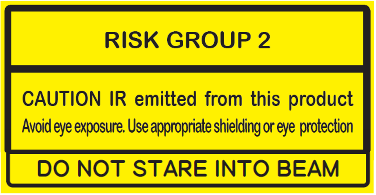
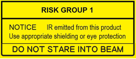
Eye Safety: The following precautions must be observed:
-
Do not stare directly into the front of the illuminator while it is operating.
-
IZSVES IR models - IEC62471 Group 2:
-
IZSVES DR models - IEC62471 Group 1:
-
IZSVES CL models - IEC62471 Group 1:
-
11.3. Legal Disclaimer
TO THE MAXIMUM EXTENT PERMITTED BY APPLICABLE LAW, THE PRODUCT DESCRIBED, WITH ITS HARDWARE, SOFTWARE AND FIRMWARE, IS PROVIDED "AS IS", WITH ALL FAULTS AND ERRORS, AND OUR COMPANY MAKES NO WARRANTIES, EXPRESS OR IMPLIED, INCLUDING WITHOUT LIMITATION, MERCHANTABILITY, SATISFACTORY QUALITY, FITNESS FOR A PARTICULAR PURPOSE, AND NON-INFRINGEMENT OF THIRD PARTY. IN NO EVENT WILL OUR COMPANY, ITS DIRECTORS, OFFICERS, EMPLOYEES, OR AGENTS BE LIABLE TO YOU FOR ANY SPECIAL, CONSEQUENTIAL, INCIDENTAL, OR INDIRECT DAMAGES, INCLUDING, AMONG OTHERS, DAMAGES FOR LOSS OF BUSINESS PROFITS, BUSINESS INTERRUPTION, OR LOSS OF DATA OR DOCUMENTATION, IN CONNECTION WITH THE USE OF THIS PRODUCT, EVEN IF OUR COMPANY HAS BEEN ADVISED OF THE POSSIBILITY OF SUCH DAMAGES.
THE USE OF ANY Inex Technologies' SOFTWARE PRODUCTS OR ANY OTHER SOFTWARE PRODUCTS REFERRED TO IN THIS DOCUMENT WITH INTERNET ACCESS SHALL BE USED WHOLLY AT YOUR OWN RISK. Inex Technologies DOES NOT TAKE ANY RESPONSIBILITY FOR ABNORMAL OPERATION, PRIVACY LEAKAGE OR ANY OTHER DAMAGES RESULTING FROM CYBER ATTACK, HACKER ATTACK, VIRUS INFECTION OR ANY OTHER INTERNET SECURITY RISKS.
For details, see the Inex Software End User License Agreement.
11.4. Regulatory Notices
-
FCC Conformance:
This device complies with Part 15 of the FCC Rules. Operation is subject to the following two conditions: (1) This device may not cause harmful interference, and (2) this device must accept any interference received, including interference that may cause undesired operation. -

 EU Conformity Statement:
This product and - if applicable, the supplied accessories - are marked with "CE" and comply therefore with the applicable harmonized European standards listed under the EMC Directive 2014/30/EU, and the RoHS Directive 2002/95/EC.
© Inex Technologies, LLC - All rights reserved.
Doc. No. IZSVES-MAN-002