IZIDPUG Installation and User Guide
Indoor AI Data Processing Unit
![]()

![]()
![]()
![]()
![]()
![]()
Click to show the Table of Contents
1. Recommended Reading/Related Documents
Click to show the Related Documents table
| Doc. No. | Title |
|---|---|
IZIDPUG Technical Data Sheet (Rev. B) |
|
IZ Discovery Utility software components |
|
IZ Discovery User Guide |
|
RoadView Documentation |
|
Software End User License Agreement (includes list of open source software) |
|
NDAA Section 889 Certification of Compliance |
2. Training and Support
2.1. Training
This document does not take the place of training by Inex Technologies' certified specialists. Contact Inex Technologies to schedule training.
2.2. Support
If you have any questions, please contact our support team via our Inex Technologies Website.
3. Checklist
-
Prepare components and tools
-
Plan your site
-
Prepare cables
-
Install components
-
Connect components (wiring)
-
Power up and set up IP
-
Verify system operation
4. Prepare Components and Tools
4.1. Package Contents
Carefully unpack the contents of the IZIDPUG package.
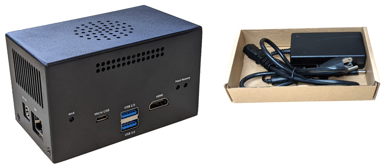
The package includes:
-
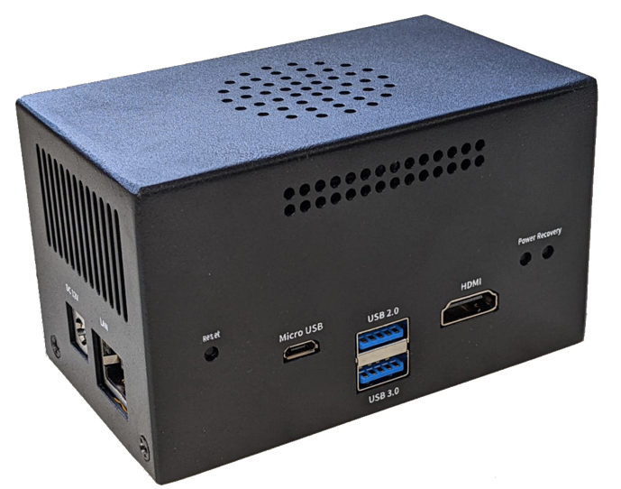
An IZIDPUG Indoor AI Data Processing Unit
-
Power adapter
4.2. Required Accessories/Tools (Not Included)
-
Network surge protector/arrestor on all network cables (see Section 5)
-
Network (LAN) cabling (typically CAT 5e/6 cable, with metal-body RJ45 connectors. The total length of the cable should not exceed 328 feet (100 meters). See Section 6 for important LAN cable information.
-
Tools for building LAN cables (wire stripper, crimp tool, etc.) and RJ45 connectors with metal bodies.
|
All network cable extensions and repeaters must be shielded. Power undervoltage, overvoltage and/or incorrect polarity will damage the unit and will void the warranty. |
4.3. Laptop Computer
-
You will need to provide a laptop computer to use for configuration. If you will be using the laptop outdoors, the screen must be able to be seen in strong sunlight. Required software:
-
Windows 10 or above - with .NET 4.5 enabled in "Windows Features"
-
Chrome or Microsoft Edge browser
-
4.5. Specifications
| Item | Specification | ||||
|---|---|---|---|---|---|
Supported Analytics |
LPR Analytics |
Plate Recognition, State of Issue, Type |
|||
Vehicle Analytics |
Vehicle Detection, Classification, Color, Make; Vehicle Without Plate |
||||
Integrated Cameras |
Inex Cameras |
IZ600F, IZB600F |
|||
3rd Party Cameras |
Any camera which supports the RTSP streaming protocol and H.264 encoding can be integrated with this AI Data Processing Unit |
||||
Processing Power |
Processing Power (fps) |
40 |
|||
Number of Cameras Supported |
Triggering Modes: |
Triggered |
Non-Triggered |
On-Demand |
|
< 20 mph (32 km/h) |
8 |
4 |
4 |
||
20-40 mph (32-64 km/h) |
8 |
2 |
2 |
||
40-80 mph (64-128 km/h) |
8 |
1 |
1 |
||
Video Input |
Streaming Protocol |
RTSP |
|||
Video Compression |
H.624 |
||||
Video Resolution |
Up to 3 MP |
||||
Supported Protocols (for additional protocols, see the RoadView documentation) |
Inex HTTP API |
LPR Events are reported via protocols such as the Inex HTTP API protocol. Each LPR Event includes metadata and associated images. |
|||
Inex Discovery |
The Inex Discovery Protocol is used by the IZ Discovery utility to find all devices connected to the LAN. IZ Discovery also enables display and editing of each device’s network settings. |
||||
AI Processor |
GPU |
NVIDIA Maxwell architecture with 128 CUDA® cores |
|||
CPU |
Quad-core ARM Cortex-A57 MPCore processor |
||||
RAM |
4 GB 64-bit LPDDR4, 1600MHz 25.6 GB/s |
||||
System and Data Storage |
250 GB |
||||
Environmental |
Operating Temperature |
32°F to 113°F (0°C to 45°C); 0.2-0.3m/s air flow; according to GB/T 2423-2008 |
|||
Storage Temperature |
-13°F to +176°F (-25°C to +80°C) |
||||
Humidity |
10% - 90% RH, non-condensing |
||||
Vibration |
1 Grms,10Hz~150Hz, 3 Axis; |
||||
ESD |
Touch 4KV, Air 8KV; |
||||
TVS |
1 KV |
||||
Certifications |
EMC |
FCC Part 15, subpart B; CE |
|||
RoHS |
EU RoHS Directive 2011/65/EU and its amendment directives 2015/863/EU (RoHS 2.0) |
||||
NDAA |
NDAA Section 889 compliant |
||||
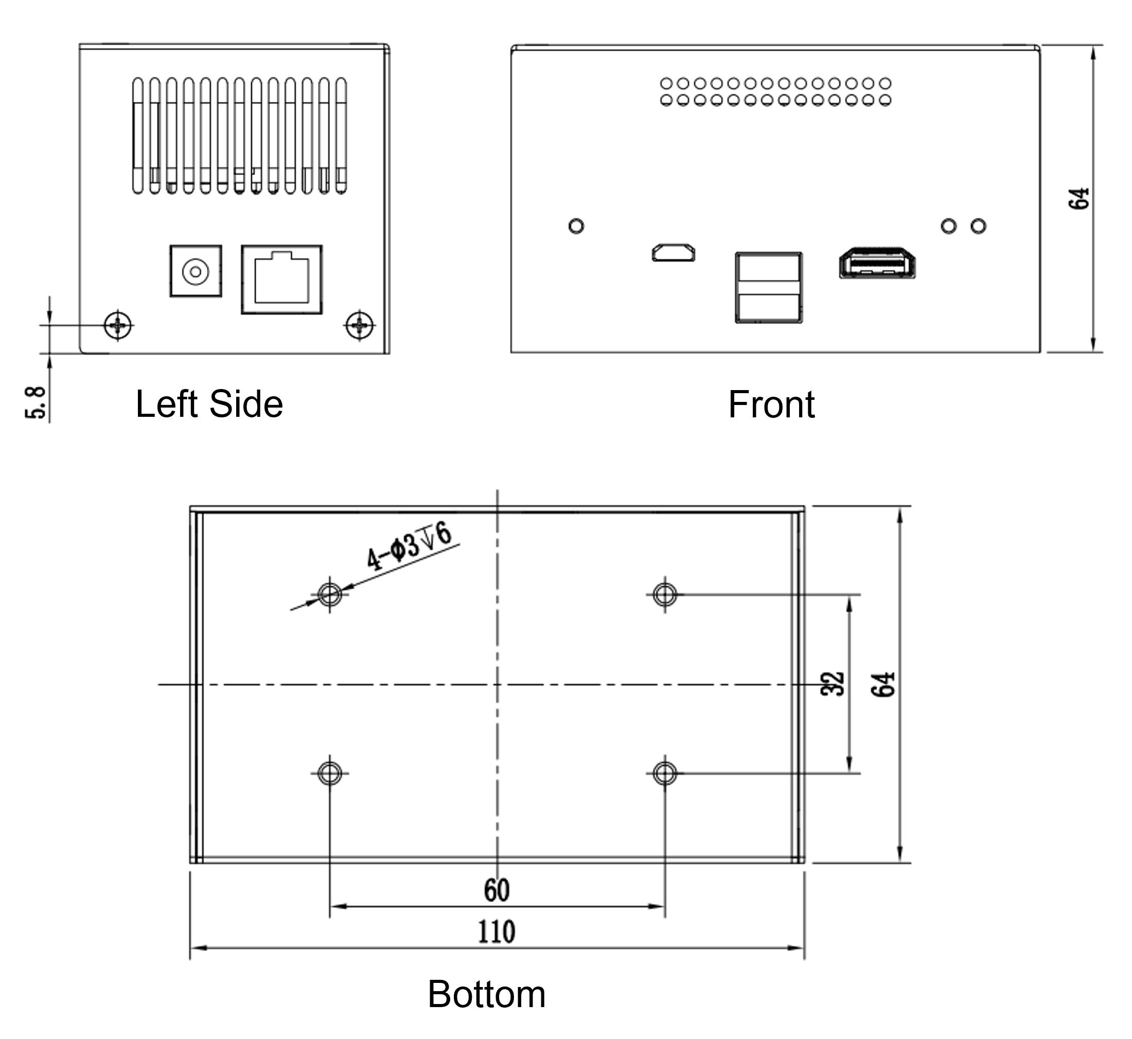
Physical |
Dimensions (W x H x D) |
4.33" x 2.52" x 2.52" |
|||
Weight |
1.05 lbs (475 g) |
||||
Color |
Black |
||||
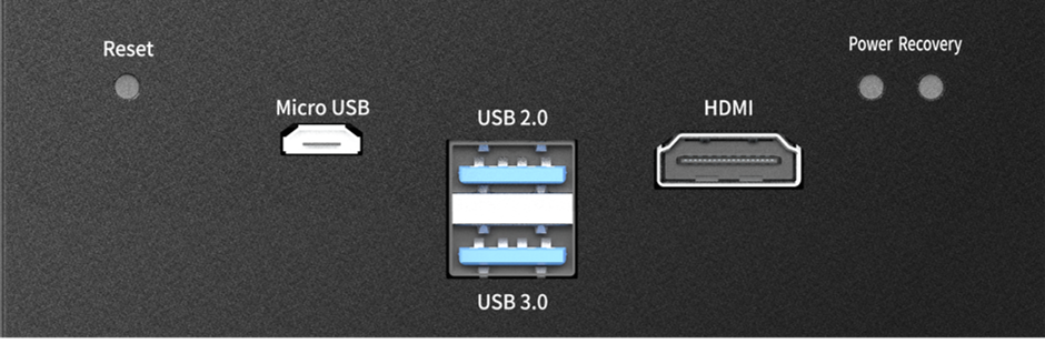
Interfaces |
Front Panel |
POWER |
Press button once for power on; |
||
RECOVERY |
(Not for user) |
||||
RESET |
Press button to reset the unit |
||||
HDMI |
HDMI 2.0, Type A, 5V, 1A |
||||
USB 2.0 |
USB 2.0, Type A, 5V, 1A |
||||
USB 3.0 |
USB 3.0, Type A, 5V, 1A |
||||
Micro USB |
Flashing port, 5V, 1A |
||||
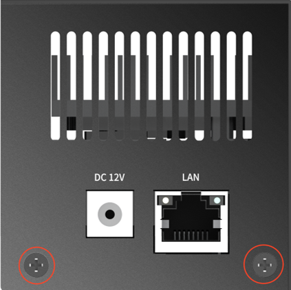
Left Panel |
DC 12V |
Power interface; male barrel socket, 12 VDC input |
|||
LAN |
1 Gigabit Ethernet port |
||||
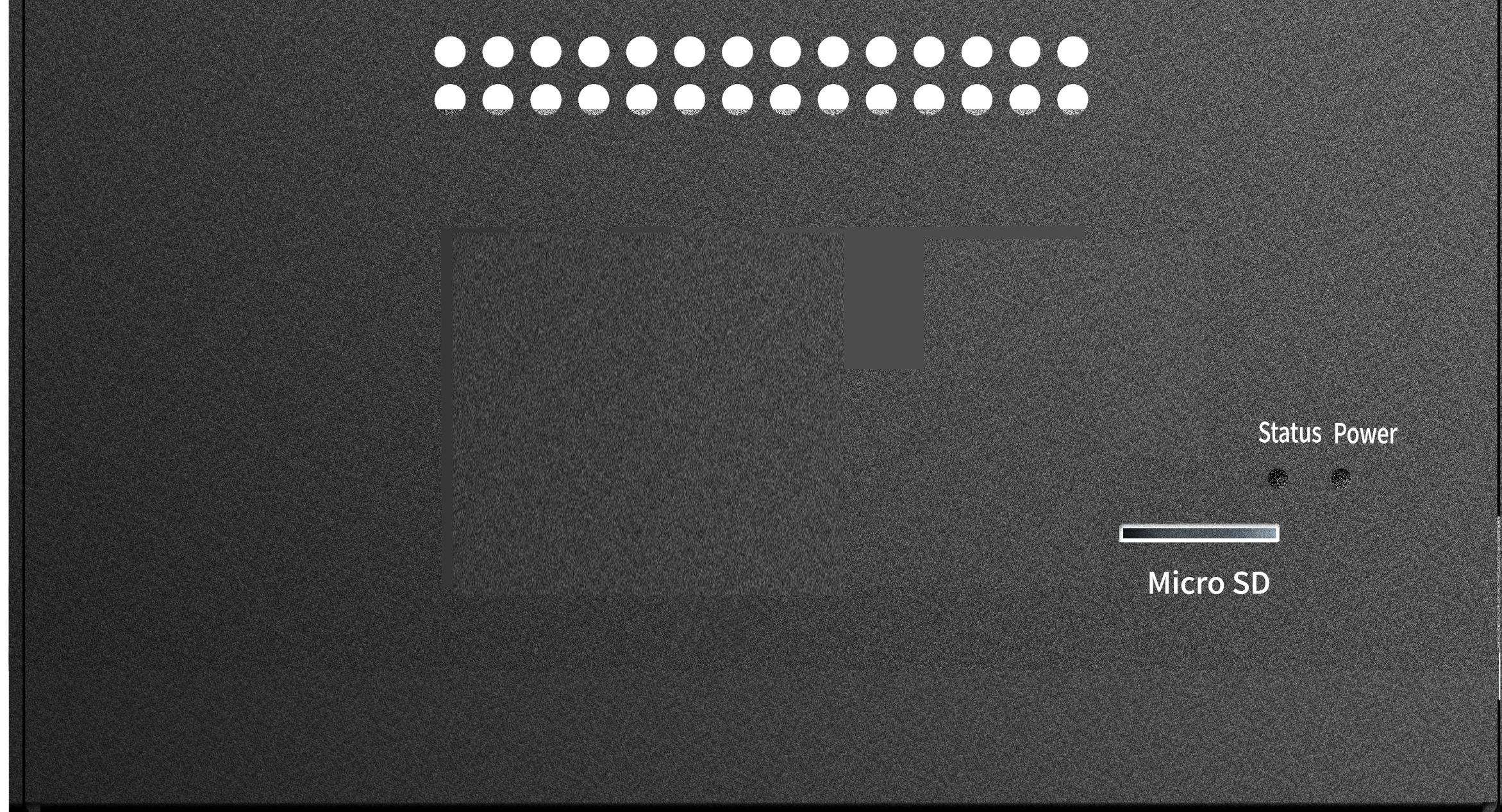
Back Panel |
Power LED |
Carrier board status indicator:
|
|||
Status LEDs |
System status indicator:
|
||||
Micro SD slot |
TF socket; for TF card 3.3 V, 1 A |
||||
Power |
Input |
12 VDC |
|||
Typical Power Consumption |
18 W |
||||
Accessories |
Accesories Included |
12 VDC power adapter |
|||
5. Plan Your Site
| Item | Considerations |
|---|---|
Surge Protection |
|
Correct, Stable and Sufficient Power |
|
Cable Extensions IMPORTANT All network cable extensions and repeaters must be shielded. |
|
Camera Configuration and Mounting |
|
6. Prepare Cables
Click to show Important notes for LAN cable construction
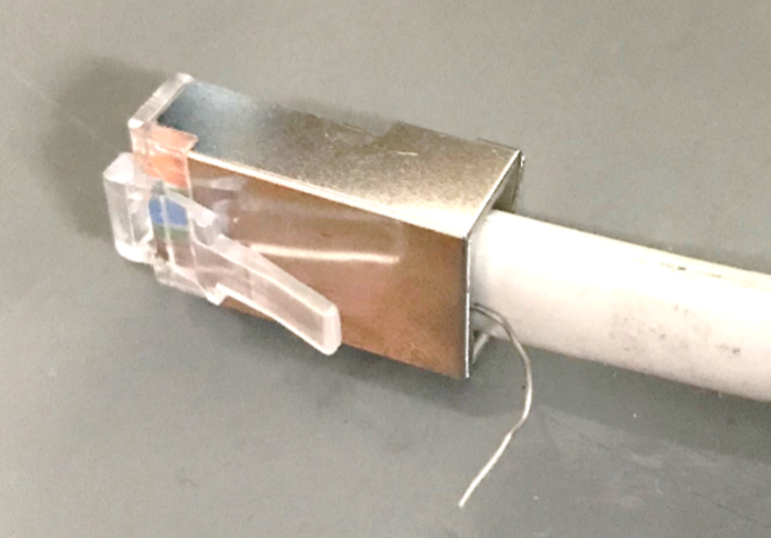
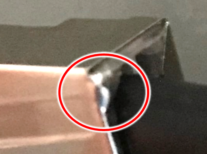
|
If you are building your own LAN cables, you must use RJ45 connectors with metal bodies. You must ensure that there is conductivity between the bodies of the connectors at each end of the cable. You can do this by extracting the cable’s shield wire before attaching the connector to the cable, and then soldering the shield wire to the body of the connector (see the following Figures). If you are using prefabricated CAT 5e/6 cables with metal-body RJ45 connectors, the shield wires have typically already been connected to each connector body. However, you must still check that there is conductivity between the bodies of the connectors at each end of the cable. |
7. Connect Components (Wiring)
|
Power undervoltage, overvoltage and/or incorrect polarity will damage the unit and will void the warranty. Turn off/disconnect the any external (AC) power supplies before connecting cables. |
|
All network cable extensions and repeaters must be shielded. |
|
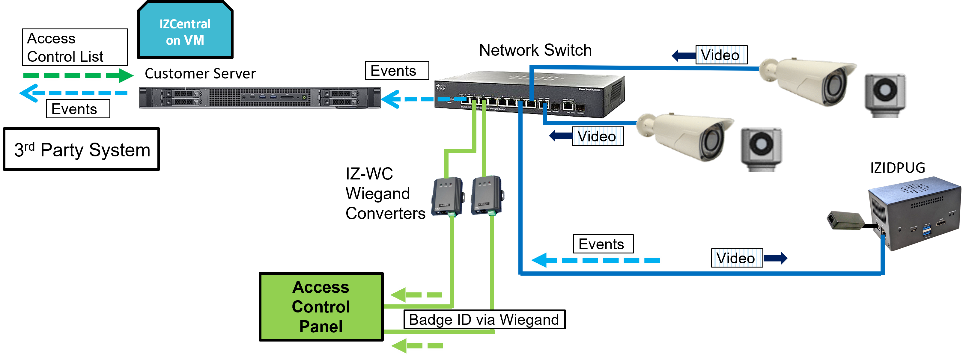
Events can be sent to IZCentral using the Inex HTTP API. Events can be sent to 3rd party systems using the Inex HTTP API and/or the Inex ZAP Protocol (see the RoadView ALPR User Guide for configuration details). See Section 1. |
8. Power Up and Set Up IP
8.1. Reserving IP Addresses in your Network
The IZIDPUG and cameras have been pre-configured with default IP addresses. You will probably need to change these addresses to conform to the requirements of your network. Be sure that you have IP addresses reserved for all components of your ALPR system (IZIDPUG and cameras).
8.2. Connecting the Power
|
If any power cables were lengthened, ensure that all components receive exactly their rated voltage. Power undervoltage, overvoltage and/or incorrect polarity will damage the unit and will void the warranty. Stable power at the correct level must be supplied to each component, even when under a heavy processing load. |
-
Connect the AC power to the IZIDPUG’s power supply
-
Plug the barrel connector into the IZIDPUG
-
Press the POWER button on the front panel
-
Verify that the IZIDPUG has started to operate properly (see Section 8.3)
8.3. Verifying Initial Operation
With power applied, you should see that:
-
The Power and Status LEDs on the back panel light up (see Section 4.6.3)
-
The LAN connector LEDs on the left panel light/flash to indicate network activity (see Section 4.6.2)
If the LEDs do not light as expected check if:
-
The cable(s) are carrying power all the way to reach the unit.
-
The LAN cable is connected properly to the unit.
8.4. Set Up IP
The IZ Discovery utility discovers all active devices connected to the network, and displays a list of their network parameters. These devices can include cameras and computers.
See the IZ Discovery User Guide (see Section 1) for instructions on how to change the unit’s IP address.
8.5. Using RoadView
8.5.1. Logging In
-
Open a browser (Chrome or Microsoft Edge). Type in the IP address of the IZIDPUG. For example:
192.168.5.110 -
You will see the login screen. Enter the default username and password (root, root):
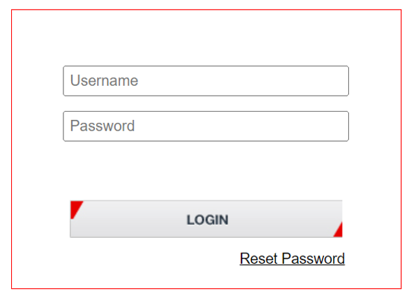 Figure 9. Logging In to RoadView
 -
You should see the RoadView Live (Journal) tab. See the RoadView ALPR User Guide for instructions for configuring and using RoadView (see Section 1).
8.5.2. Logging Out
See the RoadView ALPR User Guide (see Section 1) for logout instructions, using the multi-line dropdown menu icon in the upper right corner of the screen.
9. Verify System Operation
-
Using a license plate mounted in a lab, or by driving a vehicle through the lane, verify that an Event is generated with the correct plate read (recorded in the RoadView Live (Journal) tab - see the RoadView ALPR User Guide). See Section 1.
-
Once the lane is active, verify that Events are being generated for each vehicle passing each camera, and that the recognition has sufficient accuracy and confidence.
10. Notices, Safety Precautions and Certifications
10.1. Notice
Inex Technologies reserves the right to improve and enhance its product offerings. Thus, the illustrations and descriptions presented in this manual may differ in some respect from the products you receive.
Technical specifications are subject to change without notice.
In addition, please note that some figures are not drawn to scale, in order to illustrate the addressed issue more effectively.
All third-party trademarks are the property of their respective owners.
Inex Technologies cannot be held liable for technical and editorial omissions or errors made in this document; nor for incidental or consequential damages resulting from the furnishing, performance or use of this document.
Actions or circumstances that void the warranty are improper usage, improper handling without adequate electrostatic discharge (ESD) protection, defects resulting from natural disaster (fire, flood etc.) and unauthorized modifications or repair.
Power undervoltage, overvoltage and/or incorrect polarity will damage the unit and will void the warranty.
It is your responsibility to ensure that all wires connected to Inex Technologies' products have appropriate surge protection. Any damage due to electrical spikes (for example, lightning) is not covered by the warranty.
No part of this document may be reproduced in any form without permission from Inex Technologies.
10.2. Safety Precautions
|
BEWARE OF RISK OF ELECTRICAL SHOCK REFER SERVICING TO QUALIFIED SERVICE PERSONNEL |
|
This product must be used in compliance with local laws and regulations. All network cable extensions and repeaters must be shielded. Power undervoltage, overvoltage and/or incorrect polarity will damage the unit and will void the warranty. |
-
Please read this guide carefully before installing the unit.
-
Keep this guide for future reference.
-
Do not disassemble the unit. Repair or replacement of parts for this unit should be supplied by Inex Technologies, and installed by qualified service personnel.
-
Handle and store the unit with care.
-
Do not drop the unit or subject it to physical shock.
-
Do not allow water (e.g. rain) to enter the unit.
-
Do not handle the unit unless you have adequate electrostatic discharge (ESD) protection; otherwise, the warranty will be void.
-
You must request that your Inex Technologies-certified service technician install lightning and electrical surge protection on all wiring connected to Inex Technologies' products. The warranty does not cover surge or lightning protection.
-
Do not use the unit outside of its temperature, humidity and power source ratings as noted in its technical specifications.
-
To avoid heat accumulation/overheating, use sufficient ventilation in the unit’s operating environment.
-
Do not connect several devices to one power adapter since adapter overload may cause overheating or a fire hazard.
-
Stop using the unit immediately if it emits smoke, or if you notice an abnormal smell or sound. In such cases, please contact us. Do not attempt to repair the unit by yourself!
10.3. Legal Disclaimer
TO THE MAXIMUM EXTENT PERMITTED BY APPLICABLE LAW, THE PRODUCT DESCRIBED, WITH ITS HARDWARE, SOFTWARE AND FIRMWARE, IS PROVIDED "AS IS", WITH ALL FAULTS AND ERRORS, AND OUR COMPANY MAKES NO WARRANTIES, EXPRESS OR IMPLIED, INCLUDING WITHOUT LIMITATION, MERCHANTABILITY, SATISFACTORY QUALITY, FITNESS FOR A PARTICULAR PURPOSE, AND NON-INFRINGEMENT OF THIRD PARTY. IN NO EVENT WILL OUR COMPANY, ITS DIRECTORS, OFFICERS, EMPLOYEES, OR AGENTS BE LIABLE TO YOU FOR ANY SPECIAL, CONSEQUENTIAL, INCIDENTAL, OR INDIRECT DAMAGES, INCLUDING, AMONG OTHERS, DAMAGES FOR LOSS OF BUSINESS PROFITS, BUSINESS INTERRUPTION, OR LOSS OF DATA OR DOCUMENTATION, IN CONNECTION WITH THE USE OF THIS PRODUCT, EVEN IF OUR COMPANY HAS BEEN ADVISED OF THE POSSIBILITY OF SUCH DAMAGES.
THE USE OF ANY Inex Technologies' SOFTWARE PRODUCTS OR ANY OTHER SOFTWARE PRODUCTS REFERRED TO IN THIS DOCUMENT WITH INTERNET ACCESS SHALL BE USED WHOLLY AT YOUR OWN RISK. Inex Technologies DOES NOT TAKE ANY RESPONSIBILITY FOR ABNORMAL OPERATION, PRIVACY LEAKAGE OR ANY OTHER DAMAGES RESULTING FROM CYBER ATTACK, HACKER ATTACK, VIRUS INFECTION OR ANY OTHER INTERNET SECURITY RISKS.
For details, see the Inex Software End User License Agreement.
10.4. Regulatory Notices
-
FCC Conformance:
This device complies with Part 15 of the FCC Rules. Operation is subject to the following two conditions: (1) This device may not cause harmful interference, and (2) this device must accept any interference received, including interference that may cause undesired operation. -

 EU Conformity Statement:
This product and - if applicable, the supplied accessories - are marked with "CE" and comply therefore with the applicable harmonized European standards listed under the EMC Directive 2014/30/EU, and the RoHS Directive 2002/95/EC.
© Inex Technologies, LLC - All rights reserved.
Doc. No. IZIDPUG-MAN-002 Ver. 2024-07-01