IZA800GVES Quick Start Guide
Click here for full documentation and software.
Checklist
-
Prepare components and tools
-
Plan your site
-
Prepare cables
-
Install Camera System(s) and other components
-
Connect components (wiring)
-
Power up and set up IP
-
Configure LPR/OV camera settings
-
Aim and calibrate
-
Verify system operation
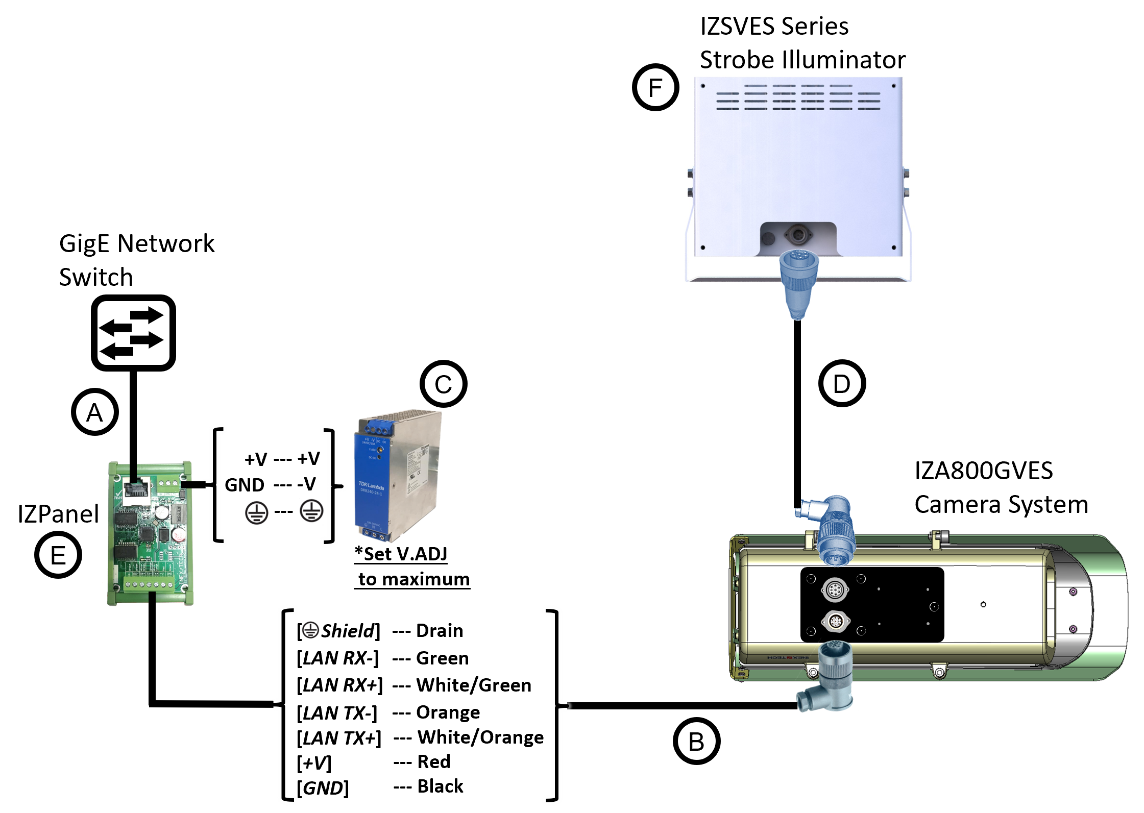
Camera System with Illuminator Wiring Diagram
|
If you attach an illuminator cable, secure or remove the connector’s protective cap to prevent it from falling (safety hazard). |
Camera System Wiring Diagram
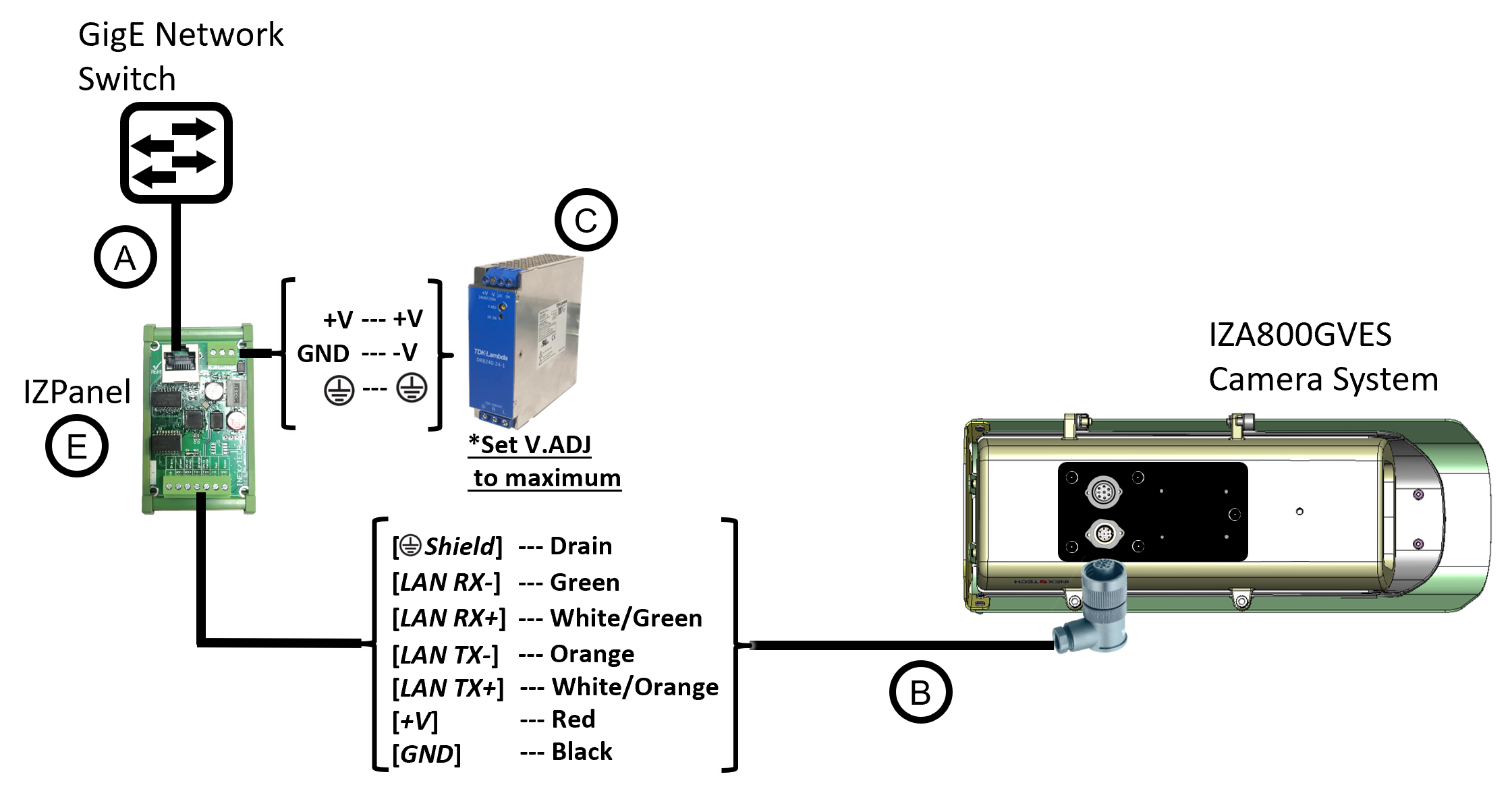
Legend
| Item | Description | Ordering Information |
|---|---|---|
A |
LAN Cable |
Supplied by integrator |
B |
Power/LAN Cable for VES System* or build yourself with IZ_COMPOSITE_CABLE and the Power/LAN Cable Connector included with the Camera System IZ_COMPOSITE_CABLE maximum allowable length is 200 ft (61 m) |
Inex P/N: IZCAB-AVES |
C |
Power Supply: 24 VDC, 240 W, DIN rail mount |
Inex P/N: IZPWR240-24-MWL-DIN |
D |
Illuminator Cable for VES System* |
Inex P/N: IZCAB-SVES |
E |
DIN Rail Mountable Connection Panel |
Inex P/N: IZPanel |
F |
Inex P/N: See the IZA800GVES Installation Guide for a table of Camera-to-Illuminator Recommended Setups |
* Different lengths can be ordered
© Inex Technologies, LLC - All rights reserved. Specifications are subject to change without notice. All third-party trademarks are the property of their respective owners.
Doc. No. IZA800GVES-TECH-001 Ver. 2024-07-01