IZA800G Quick Start Guide
Click here for full documentation and software.
Checklist
-
Prepare components and tools
-
Plan your site
-
Prepare cables
-
Install Camera System(s) and other components
-
Connect components (wiring)
-
Power up and set up IP
-
Configure LPR/OV camera settings
-
Aim and calibrate
-
Verify system operation
|
The torques required to connect the cable connectors to the connectors on the Camera System are as follows: Power/signals cable: 3-4 kgf.cm / 0.29-0.39 N.m. LAN cable: 5-8 kgf.cm / 0.49-0.78 N.m. |
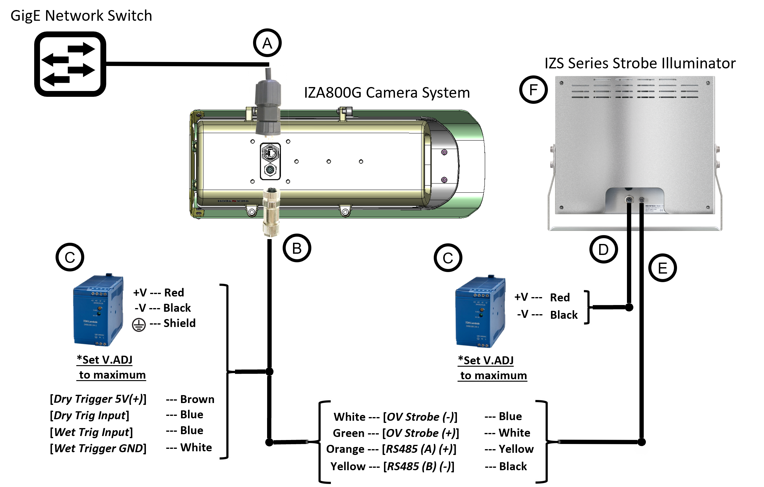
Camera System with Illuminator Wiring Diagram
Camera System Wiring Diagram
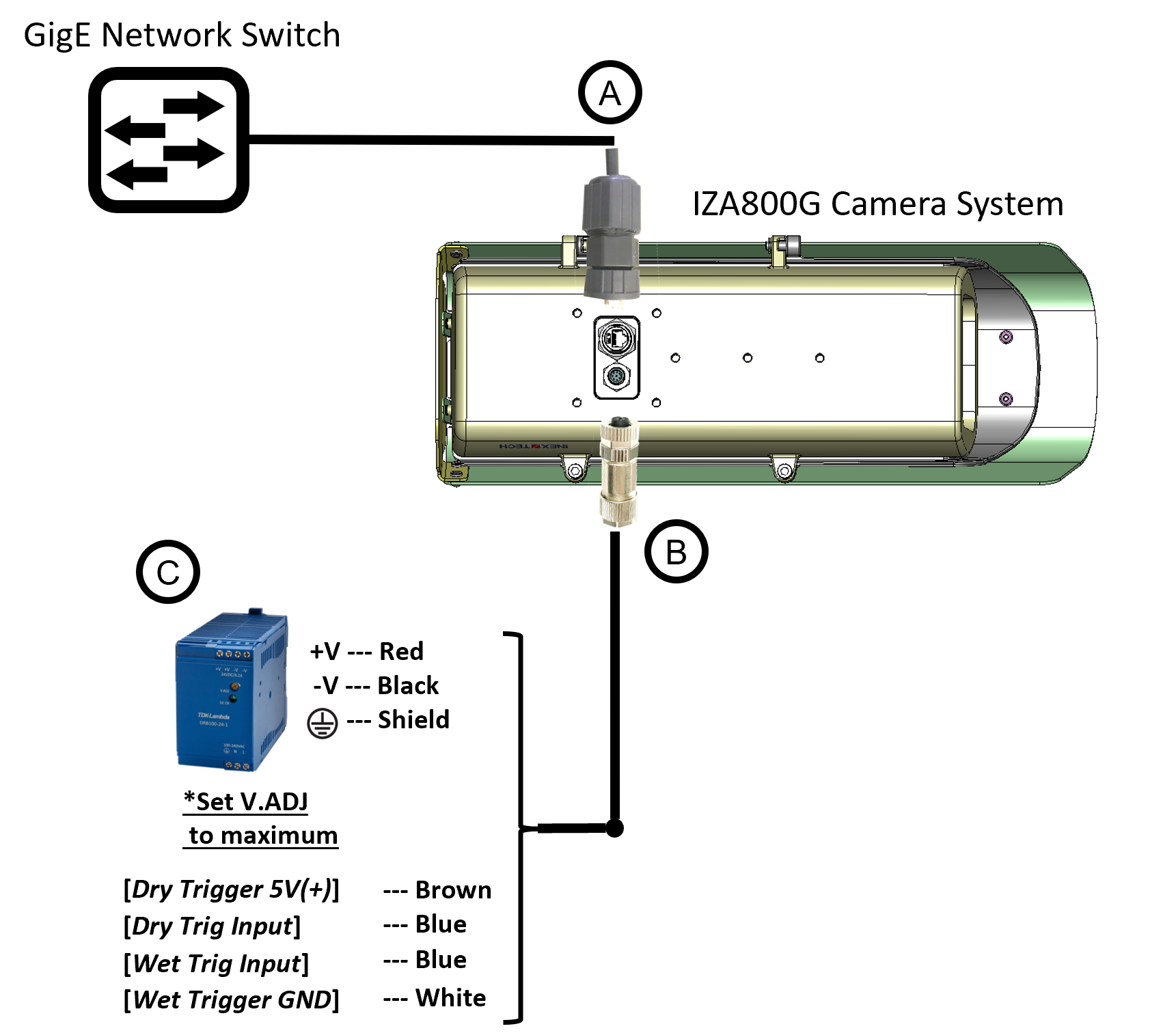
Legend
| Item | Description | Ordering Information |
|---|---|---|
A |
LAN Cable for IZA800G System* |
Inex P/N: IZCAB-A800-LAN |
B |
Power/Signals Cable for IZA800G System* |
Inex P/N: IZCAB-A800-PAS |
C |
Power Supply: 24 VDC, 100/120W; DIN rail mount Can power 2 cameras from a single power supply |
Inex P/N: IZPWR120-24-MWL-DIN |
D |
Illuminator Power Cable* |
Inex P/N: IZCAB-SPWR |
E |
Illuminator Signals Cable* |
Inex P/N: IZCAB-SSIG |
F |
Inex P/N: See the IZA800G Installation Guide for a table of Camera-to-Illuminator Recommended Setups |
* Different lengths can be ordered
© Inex Technologies, LLC - All rights reserved. Specifications are subject to change without notice. All third-party trademarks are the property of their respective owners.
Doc. No. IZA800G-TECH-001 Ver. 2024-07-01