IZA500G/GR Quick Start Guide
Checklist
-
Prepare components and tools
-
Plan your site
-
Prepare cables
-
Install Camera System(s) and other components
-
Connect components (wiring)
-
Power up and set up IP
-
Configure LPR/OV camera settings
-
Aim and calibrate
-
Verify system operation
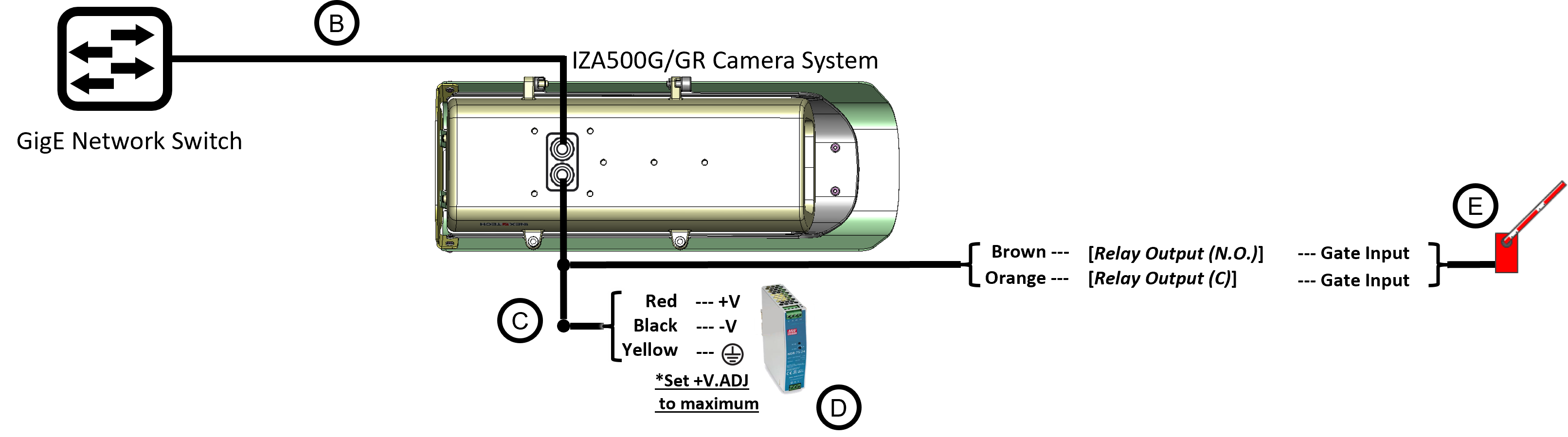
Camera System Wiring Diagram
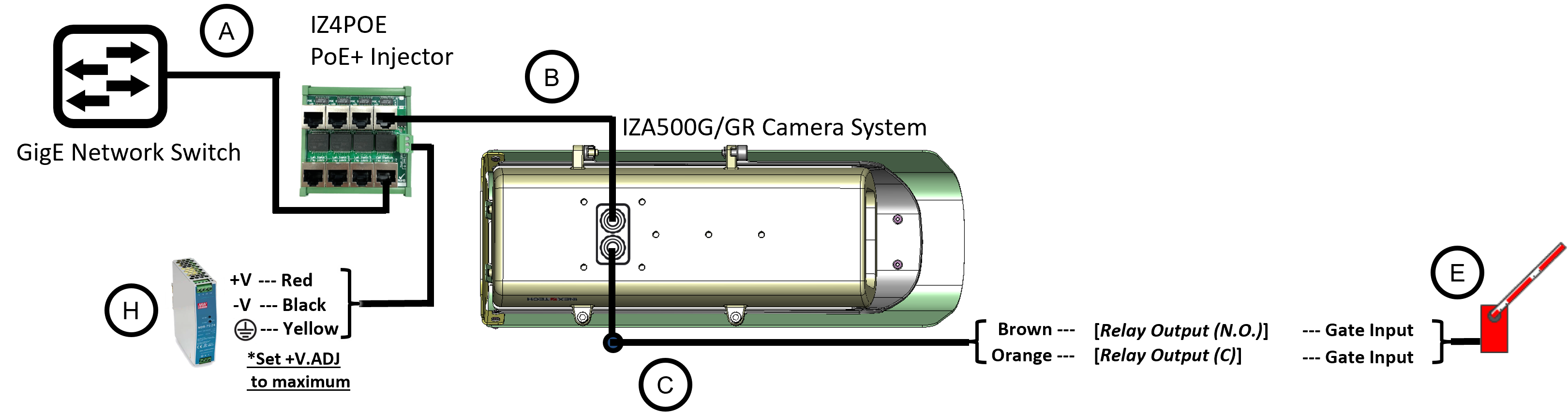
Camera System Wiring Diagram with PoE+ (P24/P48 Models)
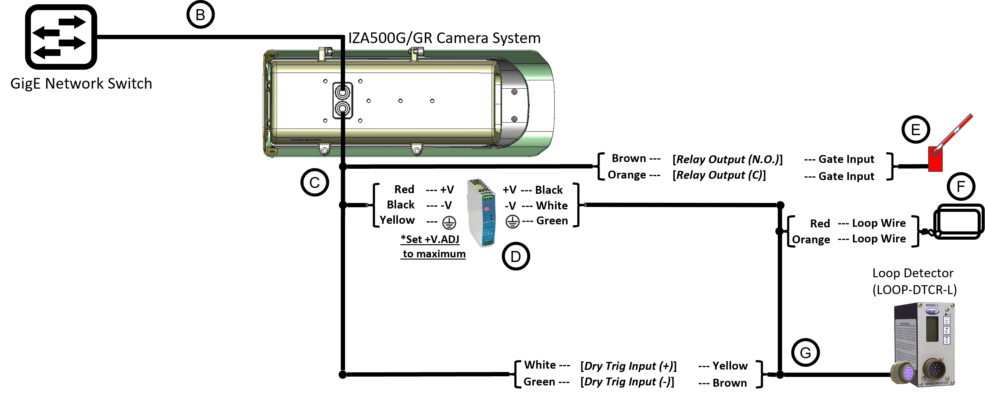
Camera System with Inductive Loop Wiring Diagram
Camera System with I/O Module Wiring Diagram
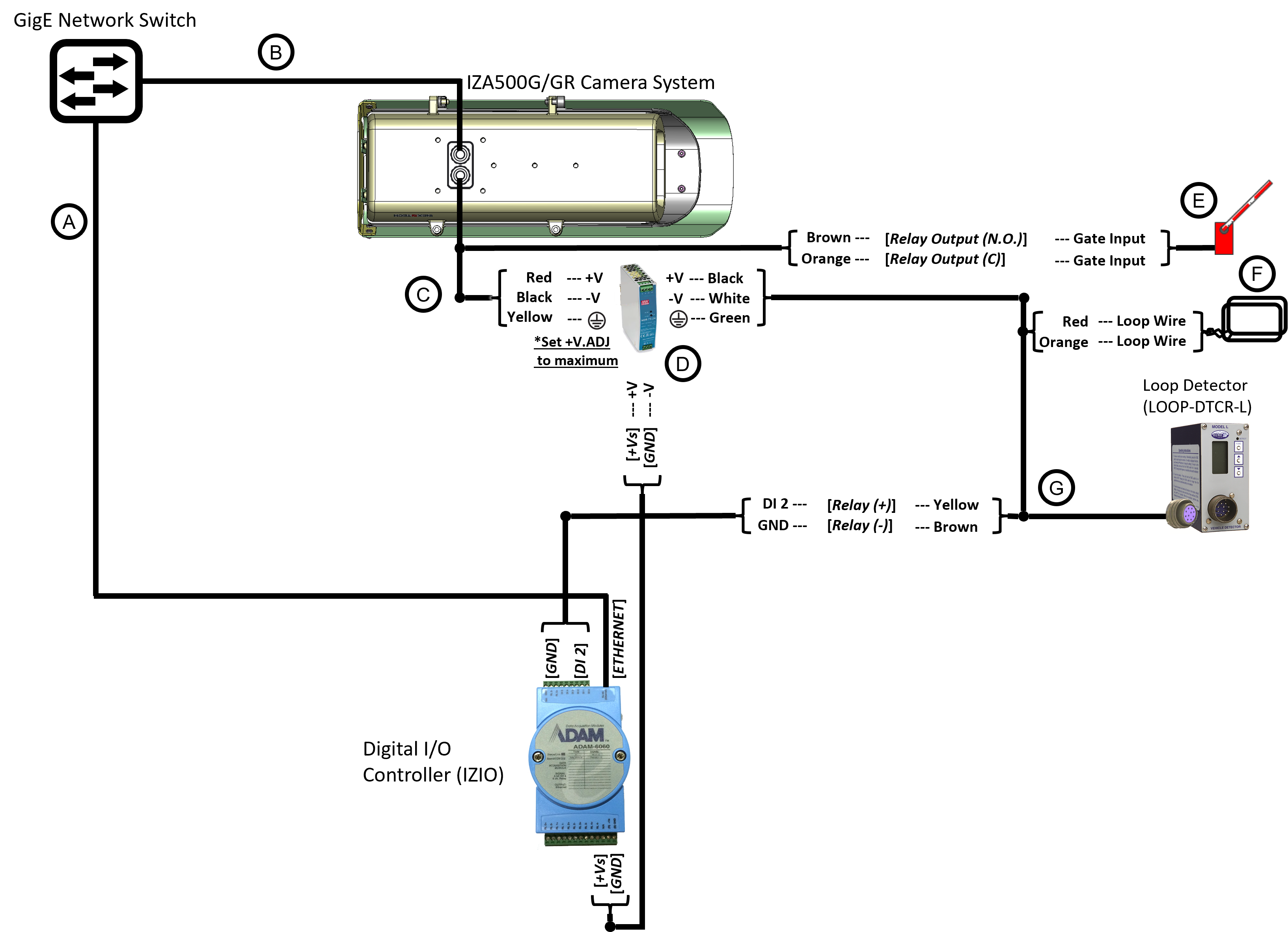
Legend
| Item | Description | Ordering Information |
|---|---|---|
A |
LAN Patch Cable - CAT6, max. length 3.3 ft (1 m) for connection to IZ4POE; |
Supplied by integrator |
B |
LAN Cable - CAT6, shielded, 4 pairs, 22 AWG, max.
length 328 ft (100 m), |
Supplied by integrator; 6.6 ft (2 m) included with camera |
C |
PAS (Power and Signals) Cable - |
Supplied by integrator; 6.6 ft (2 m) cable included with camera |
D |
Power Supply for Cameras |
|
E |
Gate |
Supplied by integrator |
F |
Inductive Loop |
Supplied by integrator |
G |
Loop Detector Wiring Harness |
Included with Loop Detector |
H |
Power Supply for IZ4POE |
For 1 camera, use a 75 W supply (IZPWR75-48) |
-
For device configuration instructions, see the LOOP-DTCR-L and IZIO guides.
-
If you need to use an external illuminator, see the IZA500G/GR Installation Guide for a table of Camera-to-Illuminator Recommended Setups.
-
The IZ4POE is required for the PoE+ input power option; a standard PoE network switch cannot be used.
© Inex Technologies, LLC - All rights reserved. Specifications are subject to change without notice. All third-party trademarks are the property of their respective owners.
Doc. No. IZA500G-GR-TECH-001 Ver. 2024-07-01