IZ600F Quick Start Guide
|
Inex products must be mounted as described in their Installation Guides. If not, moisture problems may occur - which are not covered by the warranty. |
Click here for full documentation and software.
Checklist
-
Prepare components and tools
-
Plan your site
-
Prepare cables
-
Install camera(s) and other components
-
Connect components (wiring)
-
Power up and set up IP
-
Configure camera settings
-
Aim and calibrate
-
Verify system operation
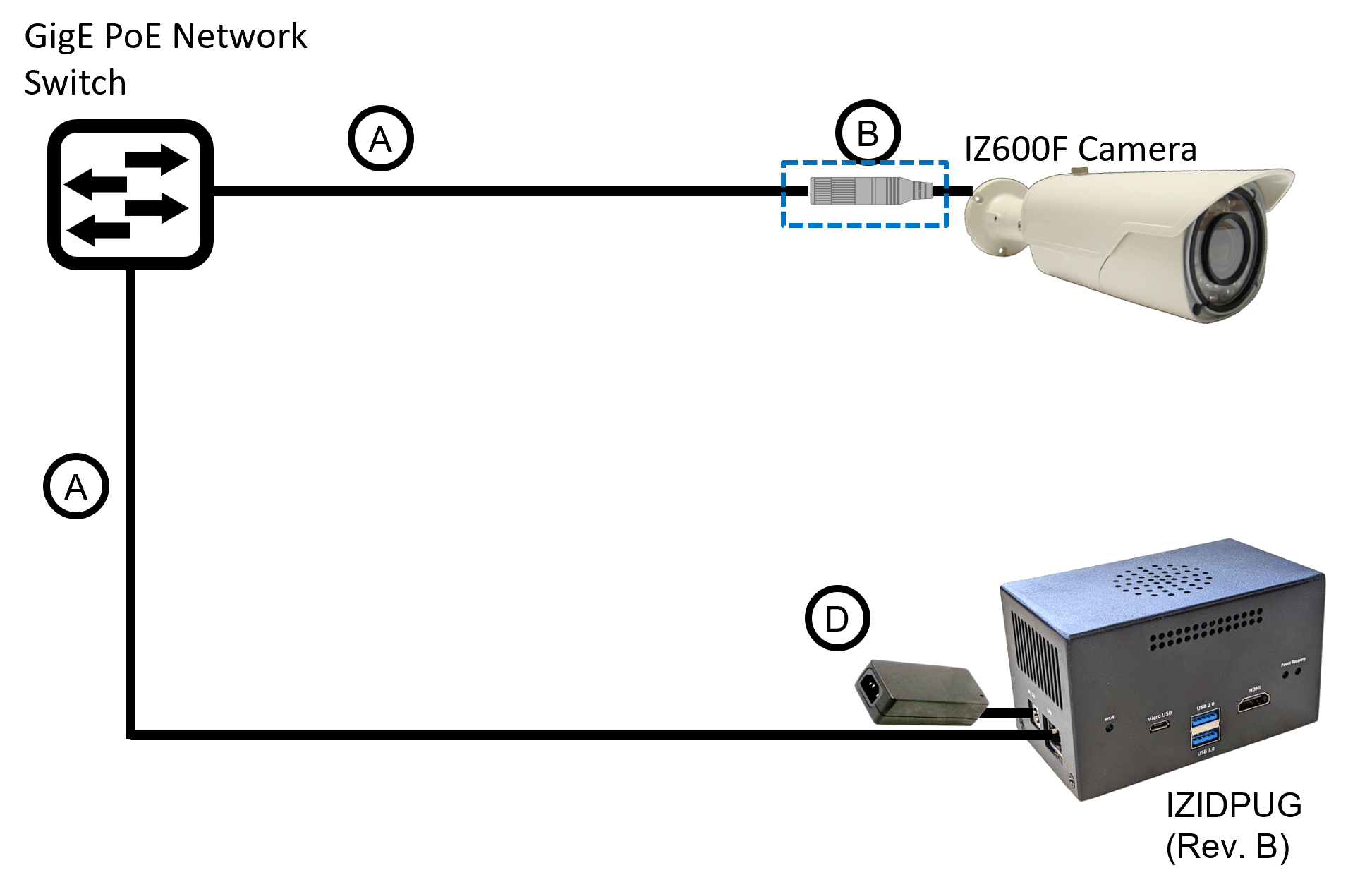
Camera with PoE Wiring Diagram
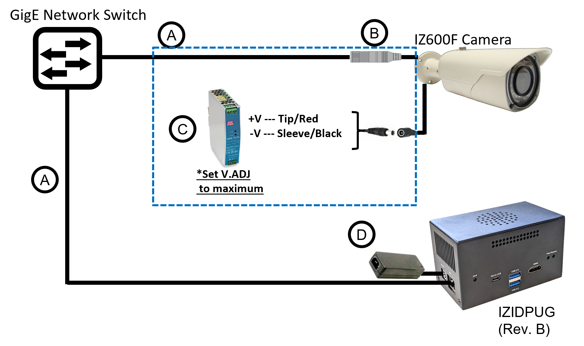
Camera with Power Supply Wiring Diagram
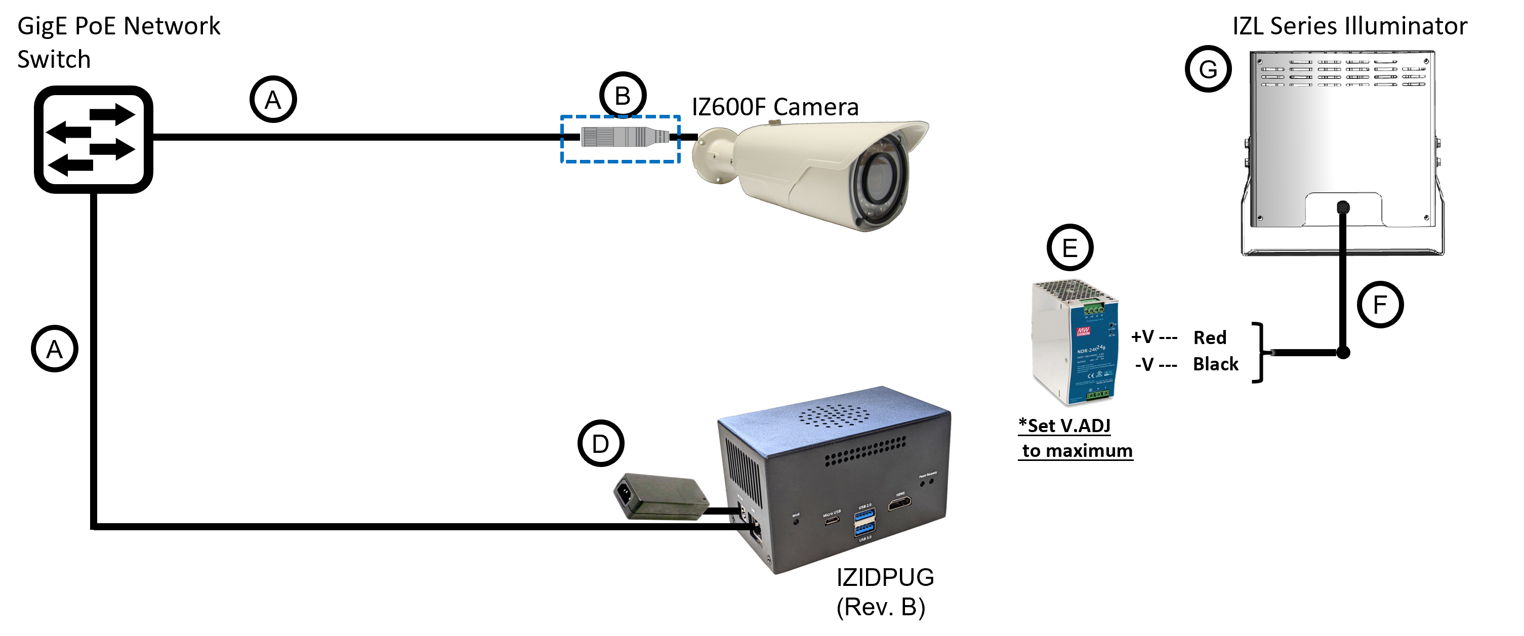
Camera with Illuminator Wiring Diagram
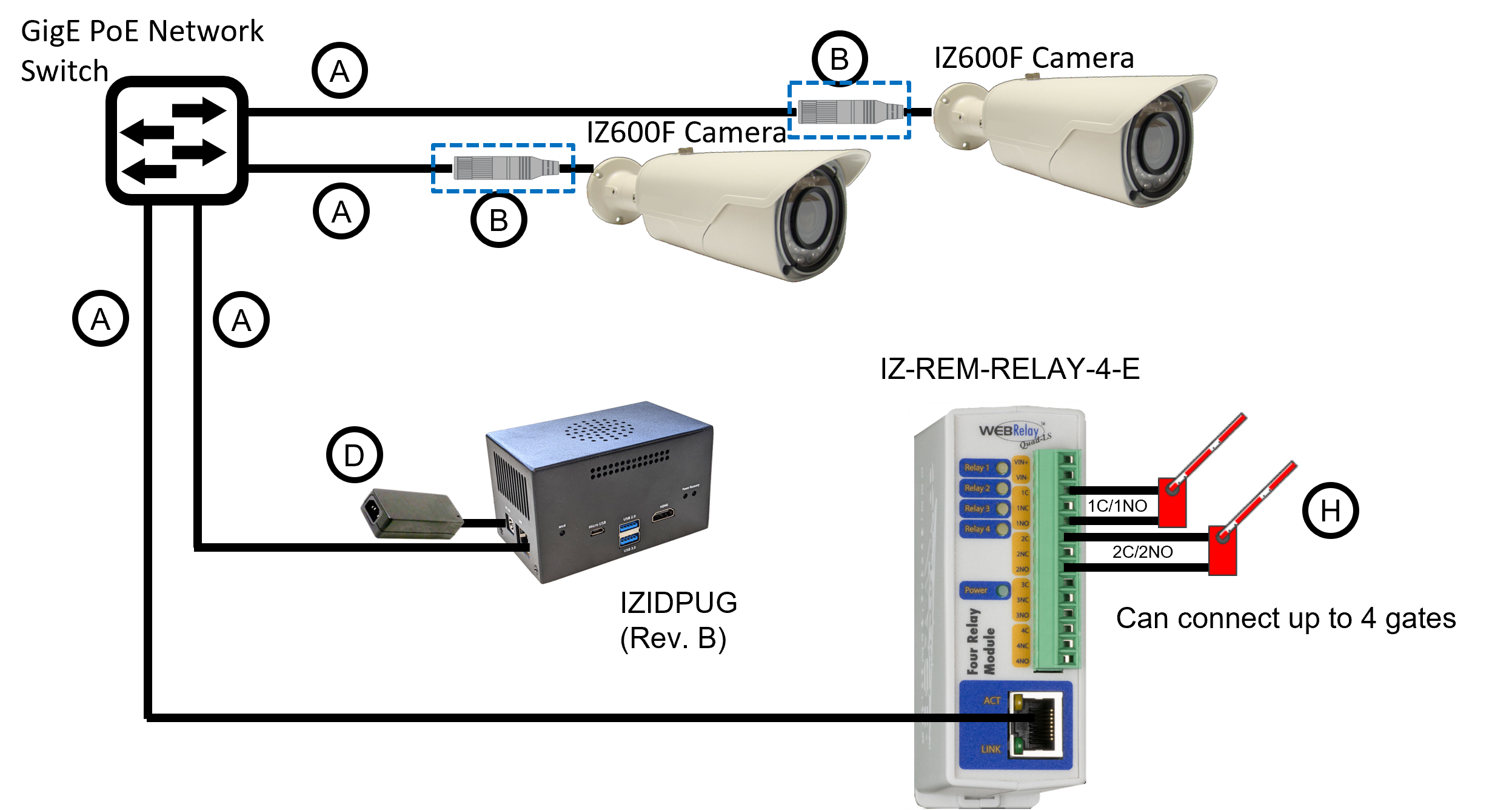
Camera with Web Relay for Gate Control Wiring Diagram
Legend
| Item | Description | Ordering Information |
|---|---|---|
A |
LAN Cables |
Supplied by integrator |
B |
Waterproof Connection Box |
Not included |
C |
Power Supply for Camera: 12 VDC,
50/75W; DIN rail |
Inex P/N: IZPWR75-12-MWL-DIN |
D |
Power Supply for IZIDPUG (Rev. B) |
Included with IZIDPUG |
E |
Power Supply for Illuminator: 24 VDC, 100/120W or 240W; DIN rail |
For IZL1, Inex P/N: IZPWR120-24-MWL-DIN |
F |
Power/Signals Cable for Illuminator |
Included with illuminator |
G |
Inex P/N: See the IZ600F Installation Guide for a table of Camera-to-Illuminator Recommended Setups |
|
H |
Gates |
Supplied by integrator |
-
For device configuration instructions, see the IZ-REM-RELAY-4 documentation.
© Inex Technologies, LLC - All rights reserved. Specifications are subject to change without notice. All third-party trademarks are the property of their respective owners.
Doc. No. IZ600F-TECH-004 Ver. 2024-07-01